Checking HVI systems
For safety during installation, approval and maintenance tests: Use the test report as a practical guide for the setting up of lightning protection systems and our services for assessing the function and condition of HVI Conductors.
Documents required for the inspection
The following documents must be available for checking an HVI system:
- General system documentation
- Documents for planning the LPS (Lightning Protection System)
- Separation distance calculation
- Installation instructions, valid at the time of installation
Prescribed test intervals
The required test intervals come from the normative specifications in IEC 62305-3 section D.7.2.2. The protection class determines the test intervals. There are exceptions after a lightning strike or structural changes, which shorten the intervals. An HVI system may only be tested by qualified, trained specialist personnel.
Criteria for the visual inspection
The visual inspection of the HVI Conductors is carried out from the supply point to the connection to the LPS (Lightning Protection System) or the earthing system. The following criteria, among others, must be checked:
I. Supporting tube
- Installation locations: were the supporting tubes installed outside Ex zone 1/21?
- Was the sealing end range of the supporting tube maintained (metal-free volume – cylinder)?
- In what condition is the shrinking of the connection elements?
- Was the aluminium tube connected to the nearest point of the system's equipotential bonding?
II. Horizontal / vertical cable routing
- Is there damage to or damage points on the HVI sheath?
- Were the permissible bending radii complied with?
- Was the minimum distance between cables routed in parallel (distance > 200 mm) maintained?
- How was the sealing end designed for connection to parapets or ring conductors?
Complete inspection
The complete inspection is carried out at different regular intervals depending on the lightning protection class or local conditions such as Ex zones or corrosive atmospheres. The difference between a visual inspection and a complete inspection is that an additional measurement is recommended for the latter: In a meshed HVI system, a loop measurement is used to check whether a low-impedance continuity (recommended value < 1 Ohm) is present.
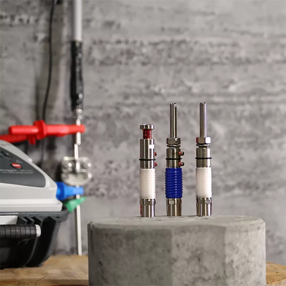
HVI check: simple function and status determination of the HVI Conductors
Both the 1-kV and 15-kV measuring methods can be used to reliably detect both mechanical and electrical damage to HVI Conductors; e.g. holes or electrical breakdown as a result of overloads.
In addition to the two measuring methods, HVI check also includes testable / insulated connection elements, insulating caps, tools and clamps. The test is to be carried out with a commercially available insulation measuring device.
Watch now:
Installation of HVI check
Watch now:
Insulation measurement of HVI check
More information on HVI Lightning Protection
Find out more about HVI Lightning Protection and what to bear in mind when it comes to separation distances.
With the high-voltage-resistant, insulated cables of the HVI systems, you can maintain separation distances without complication. The HVI (High Voltage Insulation) Conductor safely discharges lightning current from the air-termination system to the earth-termination system.
Maintaining the separation distance prevents dangerous flashovers between earthed parts of the building and the lightning-current-carrying components of the lightning protection system.
Downloads
HVI Check
Dielectric withstand test for HVI Conductors
Test instructions
Insulation testing on high-voltage-resistant, insulated down conductors
Test report
HVI Lightning Protection system inspection
Installation instructions
HVI light plus – insulated connection elements


